
Mill Creek Central Turntable Project
The railroad is expanding up the big hill to the west of the main yard. There will be a long grade that may tax the capability of some locomotives pulling a long train. The plan is to follow the practice of many operating railroads and provide a pusher locomotive for the long grade. It would be possible for the pusher to return down the hill backwards however it would be much nicer to have a way to turn the pusher around at the top of the grade. (There will be a wye below the long hill going into the main yard.) A wye was considered for the meadow at the top of the hill but there is insufficient flat area perpendicular to the north-south direction of the track. An alternative is a turntable.
Jim Zealer uses an auto hoist piston-cylinder unit for a hoist to assist in loading/unloading as well as a turntable. He mounted a pair of 4" channels to the top of the piston to serve as the round table track. The piston rotates relatively easily inside the cylinder serving as a center bearing. We have several auto hoists units but are reluctant to use them in the meadow because we don't want to deal with the pneumatics and hydraulics. What would be nice it to be able to find a really strong shaft with flange and shaft bearings. A robust pickup truck rear axel came to mind.
A call to several auto salvage yards proved fruitless; they needed to know the precise make and model of rear end. Next, the local junk yard (a place that scrapped the vehicles) was called and asked for a robust Ford pickup truck rear end. After a couple shouts around the office they said they had one ----- $50. We went over and picked it up immediately before they changed their mind.

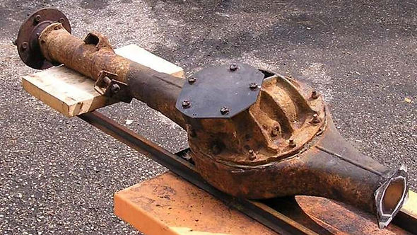
Photo above shows the rear end. We didn't know what we had so an expert on Ford products was consulted.. He said it's a Ford 9" rear end, one of the best made. He referred us to several websites with more information. Check out: http://www.kevinstang.com/Ninecase.htm
The center bearing for the axel is contained in the differential gear assembly so the differential case must be included in the "turntable center bearing assembly". One axel, most the axel housing on one side and the pinion can all be removed. .
The modified rear end is shown in photo above. The end on the right was cut off and a cover welded over the hole. The pinion and associated bearing housing were removed and a crude cover installed over the hole. Gaskets and sealer were used under the cover to make it oil tight. The hub, brake backing plate and associated brake hardware were also removed .
This photo shows a partially removed axel. The plate between the bearing and the flange is bolted to the end of the axel housing to retain the axel and bearing in the housing. Once the four nuts are removed, the axel slides out (a little force is required to move the bearing seal). Once the axel is out the the brake backing plate can be removed.
This is what the axel looks like. In fact, this is the spare axel which figures into our plans.
We have the bearing, what next?


The turntable above was discovered on a trip to the mountains around Peje, Kosova a couple years ago. This is about the size we need to model.

This is a little better view of one end of the turntable. It is supported by the wheels on the ends that ride on a rail fastened to the circular concrete shelf. The wheels have no flanges so there must be a bearing in the center to keep everything centered. (We hiked in the mountains in the background; it was a beautiful day.)
This photo shows the gears inside the little house. The turntable seemed to be manually powered. That looks like a partially visible crank at the far end of the upper shaft.
This is the drive wheel on the outside of the gear house.


The wheels on the outer edge of the round table make everything very stable. However, we don't want to try to bend rail or something similar --- that seems to be too much work. A circular concrete pad seems easier. We don't need a drive mechanism ------- we can push it around. The flange on that Ford axel is forged and really strong; we're pretty sure it can take the torque caused by a locomotive rolling onto the round table, especially if we make the roundtable as short as possible, on the order of 16'. So, we decided to try supporting the roundtable only on that center bearing.

Photo above shows the Mill Creek Central transfer table. The track across the top is a pair of 20' long 4" x 1/4" channels supported a couple feet from each end. The center flexes under load but only about 1/4" for a pretty heavy locomotive. We decided to use this type channel for the rails on the round table.
So, the plan is:
-
Mount the bearing unit (the modified Ford rear end) upright in concrete with the flange just above ground level .
-
Make a 12" square 1/2' thick adaptor plate that bolts to the axel flange.
-
Weld a pair of 16' long 4" channel rails to the adaptor plate.
-
Try to use the turntable with only the center support.
-
If the flange breaks, or if the ends sag, go to Plan B.
Plan B:
-
Pour a circular concrete pad near the perimeter of the roundtable.
-
Replace the axel & flange (if broken) with the spare.
-
Support the ends of the channels with large casters rolling on the circular concrete pad.
The track across the meadow won't be ready until next spring. However, we have several concrete projects planned before winter so we went ahead and installed the bearing and deck to test it to see if we have to go to Plan B. The bearing unit was installed in concrete a few weeks ago. Photo above shows Wayne Godshall bolting the turntable deck to the axel flange. Bruce Werner is steadying the deck --- it turns really easy. (That's the tunnel mouth in the background. We laid out some track and switches to help judge the best position for the turntable. It's been an usually wet fall and a good test of the grade and drainage. The grade looks great and drainage is excellent. We did find a couple minor trouble spots that can be fixed before the track goes down. )
This is a close up of the center of the deck. Bob Miller made the adapter plate using a brake drum for a pattern Bruce then welded up the deck.


The Test: Bruce got on the end as a first test. The end of the deck sank a little, but flange didn't break.. Then Dick got on with Bruce and the end really sank. However, no problem with the flange. What is happening is the axle and flange are lifting slightly and the axel is flexing a little. (You all can estimate the load these two put on the end )
So, it's on to Plan B. We'll use the deck to position the form for the concrete circle. We'll pour the concrete when we do one of the other projects. With luck, we'll have the turntable finished by Thanksgiving.


Update 12-2-2006: We missed Thanksgiving but did manage to pour the concrete circle the next week. Photo above shows Denny Varian finishing the top of the circle. The dirt banked against the form on the inside of the ring was shoveled out after the concrete cured. We have all winter to put the wheels on the deck and then install it. The track from the tunnel to the trestle will be in the upper part of the photo. By spring that track should be in place.
Update 12-16-2006: We have been blessed with unseasonably warm weather this month --- maybe that makes up for the unseasonably cold weather in October. The warm weather allowed us to do a lot of track work and to finish the turntable as shown above. The wheels have a wide flat flange which rides on the concrete. Two of the wheels have gear teeth cut in the flange. If the wheels start to damage the concrete we'll install a rail for the wheels to ride on.
Photo above was taken from the meadow south of the turntable. The right two tracks are the main line with passing siding which become a single tack that passes to the the right of the turntable and then curves to the left to enter the tunnel which is visible behind and to the left of the backhoe. A track from the north side of the turntable will join the mainline via a switch just to the right of the backhoe. The left track is a siding. The track from the left side of the switch in this siding will lead to the south side of the turntable.
Photo above was taken from the north side of the turntable and shows the meadow south of the turntable. The main line (left two tracks ) curves to the right behind the slight rise to reach the north end of the trestle.
The turntable is essentially finished at this point. We'll come back and add some photos of the turntable in operation ---- probably next spring.


Update October 29, 2007 - Operation: The turntable has operated all summer without any problem.
Matt Kerr took the following series of photos in late summer showing Nelson turning around the MCC switcher.
This shows backing onto the turntable from the south.
The switcher is all the way on.
The alignment plate is slid out of the gap and the rotation is started.
It's pretty easy to turn even the big steamers
Just about there.
Slipping the alignment plate into position.
Driving off --- hardly any bump.
Just about off...
On the way down the hill ---- pointed in the right direction!


Update 5-12-2008: As mentioned previously, two of the wheels supporting the turntable have gear teeth cut in the wheel flanges. These teeth were starting to wear into the concrete pad. We anticipated that there might be a problem and made the wheels adjustable initially so that a rail could be installed under the wheels.

We installed a rail under the the wheels this spring as shown in the photo above. It works great!
The sliding board alignment devices are viewed by many as a bit primitive so that is on our list of future improvements. We may be able to come up with a design that includes a stop at the ends of the turntable to prevent the equipment being rotated from rolling off when the turntable is being rotated. (Continuous improvement of the ISO 9002 style is incorporated in all MCC processes.)